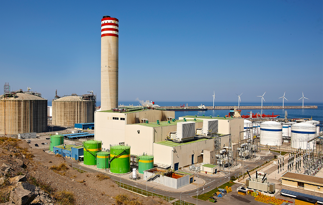
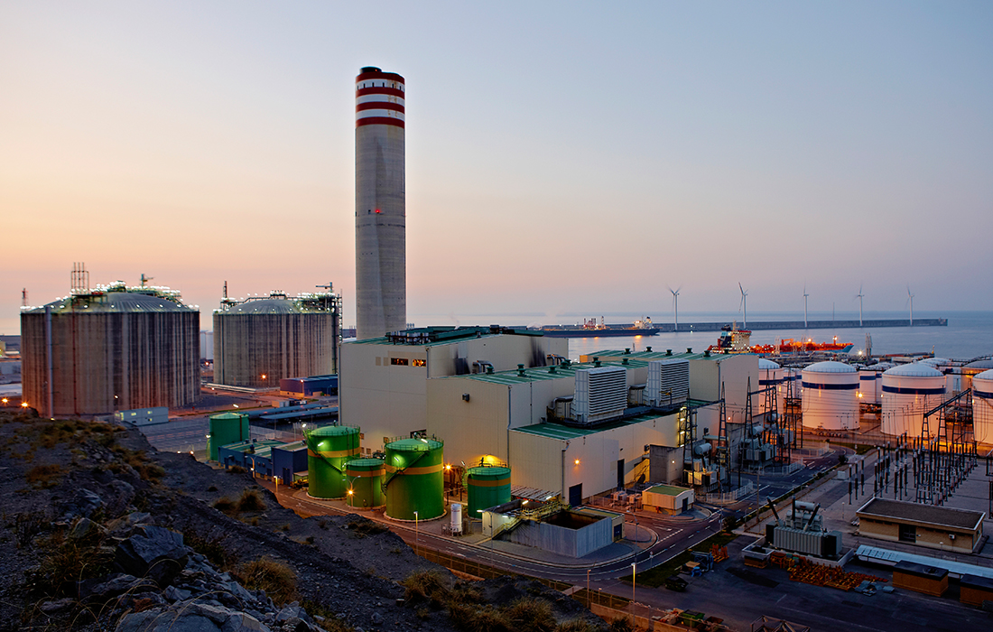
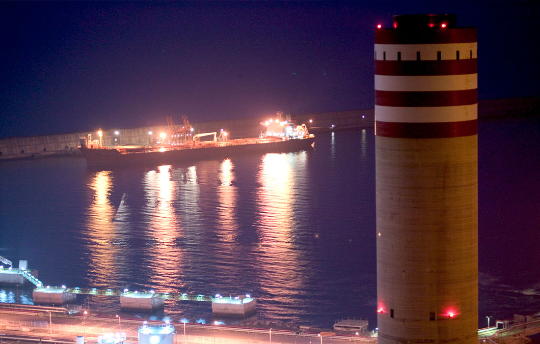
BBE’s Combined Cycle Power Plant is located on a plot of land of approximately five hectares, situated on the excavated site at Punta Lucero for the extension of the port of Bilbao.
Do you want to know it?
Plant Overview
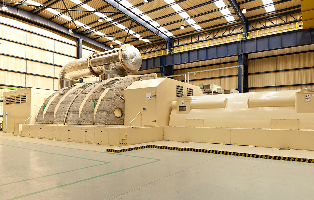
Heat cycle
AUXILIARY SYSTEMS
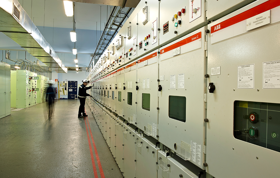
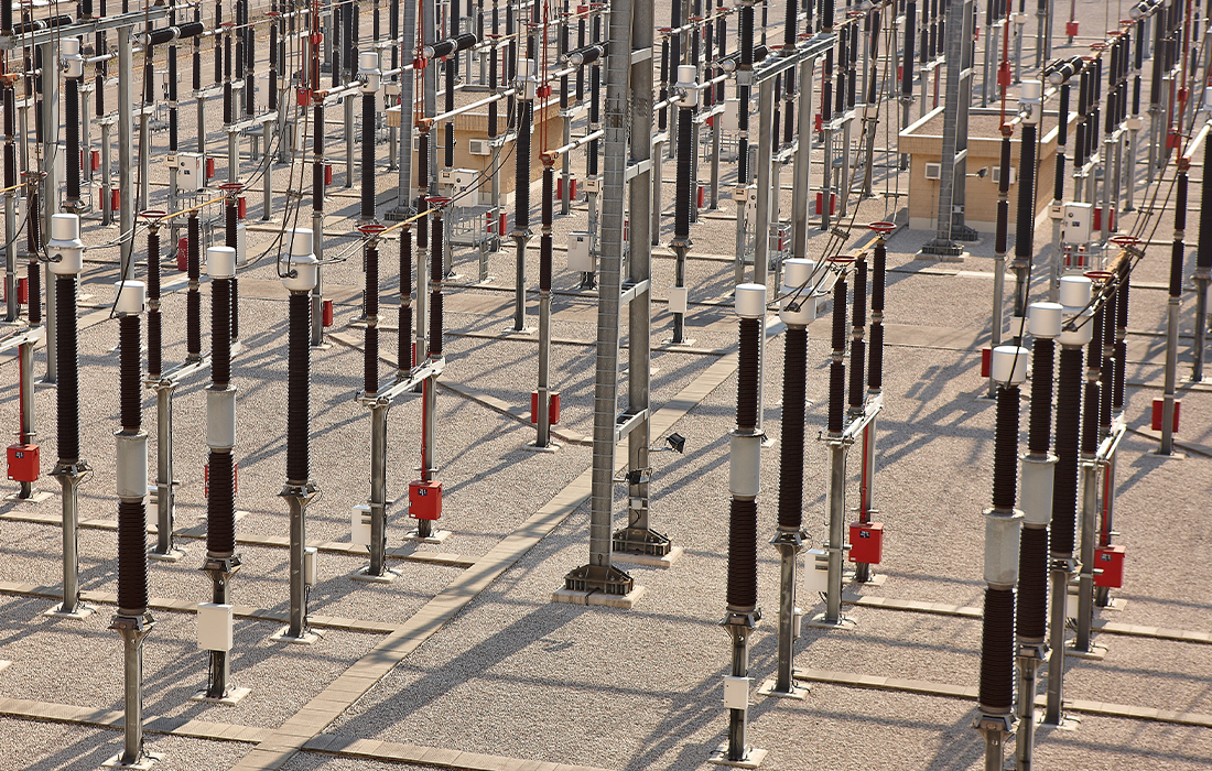
ELECTRICAL SYSTEM
SUPERVISION AND CONTROL SYSTEM
AREAS OF DE POWER STATION
We use our own and third-party cookies to ensure you as the user get the best experience on our website.More information about cookies.
This website uses cookies so that we can give you the best possible user experience. Cookie information is stored in your browser and performs functions like recognising you when you return to our website and helping our team understand which website areas you find most interesting and useful.
Necessary cookies activate basic functions like navigation and access to secure website areas. Without these cookies, the website cannot work properly.
Cookie
Type
Duration
Description
cookielawinfo-checkbox-necessary
persistent
11 months
This cookie is set by the GDPR Cookie Consent plugin. It is used to store user consent for the cookies in the “Necessary” category.
cookielawinfo-checkbox-non-necessary
persistent
11 months
This cookie is set by the GDPR Cookie Consent plugin. It is used to store user consent for the cookies in the “Non-Necessary” category.
viewed_cookie_policy
persistent
11 months
This cookie is set by the GDPR Cookie Consent plugin and is used to store whether or not the user has consented to the use of cookies. It does not store any personal data.
Marketing cookies are used to track website visitors. The aim is to display adverts that are relevant and appealing to the individual user.
Cookie
Type
Duration
Description
IDE
persistent
2 years
This cookie is used by Google DoubleClick and stores information about how the user interacts with the website and any other advert before visiting the website. This data is used to present the user with adverts that are relevant to them based on their user profile.
uid
persistent
1 month
This cookie is used to anonymously measure the number and behaviour of visitors to the website. This data includes the number of visits, average visit duration, pages visited, etc. to better understand user preferences for targeted adverts.
VISITOR_INFO1_LIVE
persistent
5 months
This cookie is set by YouTube. It is used to track information for YouTube videos embedded on a website.
Statistics cookies help website owners understand how visitors interact with web pages. Information is collected and provided anonymously.
Cookie
Type
Duration
Description
__utma
persistent
2 years
This cookie is set by Google Analytics and is used to distinguish users and sessions. It is created when the JavaScript library executes and there are no existing __utma cookies. It is updated every time data is sent to Google Analytics.
__utmb
persistent
30 minutes
This cookie is set by Google Analytics. It is used to determine new sessions/visits. It is created when the JavaScript library executes and there are no existing __utma cookies. It is updated every time data is sent to Google Analytics.
__utmc
session
End of browser session
This cookie is set by Google Analytics and is deleted when the user closes their browser. It is not used by ga.js. It is used to enable interoperability with urchin.js, which is an older version of Google Analytics and used in conjunction with the __utmb cookie to determine new sessions/visits.
__utmt
persistent
10 minutes
This cookie is set by Google Analytics and used to throttle the request rate.
__utmz
persistent
6 months
This cookie is set by Google Analytics and used to store the traffic source or campaign through which the visitor reaches the site.
_ga
persistent
2 years
This cookie is used to distinguish users and sessions.
_gid
persistent
1 day
This cookie is used to distinguish users and sessions.
GPS
persistent
30 minutes
This cookie is set by YouTube and registers a unique ID for tracking users based on their geographical location.
test_cookie
persistent
11 months
Google DoubleClick can set this cookie on our website to check whether the user’s browser accepts cookies. Google DoubleClick aims to improve the advertising the user sees.
YSC
session
End of browser session
This cookie is set by YouTube and is used to track views of embedded videos.